‘Satellites for Earth Observation’ is the English translation of the French words Satellite Pour l’Observation de la Terre and a familiar notion in the remote sensing domain. Its abbreviation SPOT refers to the satellite program initiated by the French space agency in the 1970s (CNES (Centre national d’études spatiales) in collaboration with Belgium and Sweden. SPOT satellites have been developed to deliver high resolution satellite imagery. Already the launch of SPOT1 in 1986 brought a revolution in space technique being the first satellite equipped by mirror technology being able to take photos from the left and right side of the track.
The family grew with SPOT 2,3 and 4 all featuring similar performance – non of them is working today with SPOT4 running until 2013. SPOT5 has a better spatial resolution of 2,5m in panchromatic mode than the previous models, was launched in 2002 and is still working.
SPOT 6 and 7 open a new era of SPOT technology. They are marked by a higher horizontal resolution, improved coverage capabilities, impressive reactivity and enhanced image quality. SPOT6 entered its orbit in 694m altitude (the same as Pléiades 1A and 1B) in September 2012, the constellation is planned to be completed with the launch of SPOT7 in 2014.
NEW AGILITY
The new SPOT are very agile. The control moment gyros system (CMG) allows the satellites to pitch and roll forward, backward and sideways up to 45º very quickly – twice as fast as earlier designs increasing the number of images that can be collected during the same pass. Other satellites, even if they work quickly, do not swing and re-target at the same speed.
SPOT 6 and 7 have more opportunities to collect images, which imply scheduling conflicts between contiguous requests are greatly reduced and the average acquisition window is much narrower. Due to those features, SPOT 6 and 7 can cover entire countries fast. Therefore, the request of Mali Cartographic Institute to provide an image covering the entire country’s surface of 1.25Mill km² without clouds, dust or storms could be handled only within 5 months.
Additionally, the new satellites can shoot images vertically to the earth’s surface. Those nadir images deliver more complete and accurate sceneries as low-lying objects are not hidden from view as they may be in the oblique perspective resulting in more accurate digital elevation models.
A FEATURES OVERVIEW
- A multitude of individual scenes in a reduced theatre – typically 11 within a 1,000km-long orbit slot
- Long strips, with a maximum length of 600km: this is the typical acquisition mode for SPOT 6 and SPOT 7.
- Contiguous strips – for example, to cover an area of 330km x 300km in a single pass that can then be automatically orthorectified in the ground segment : the generation of a fully orthorectified 60km x 60km colour image is achieved in less than 50 minutes and more than 20 products can be processed in parallel.
- Corridors (segments with an orientation other than north to south) to cover a border, a coast line, a shipping route or any linear feature.
- Stereo collection for 3D model computation and mapping up to 1:15,000.
- Enhanced quality due to 12-bit pixel depth; in contrast to the usual 8 bits pixel depth one pixel may take up to 4.096 different values (colours) instead of 256.
- Addition of blue colour band at SPOT 6 and 7 enhances photointerpretation and consequently new applications as for instance the penetration/discrimination of water surfaces for coral reef mapping and bathymetry – I reported in my article about the mapping of the Great Barrier Reef that the blue band is used for bathymetry and water column specification
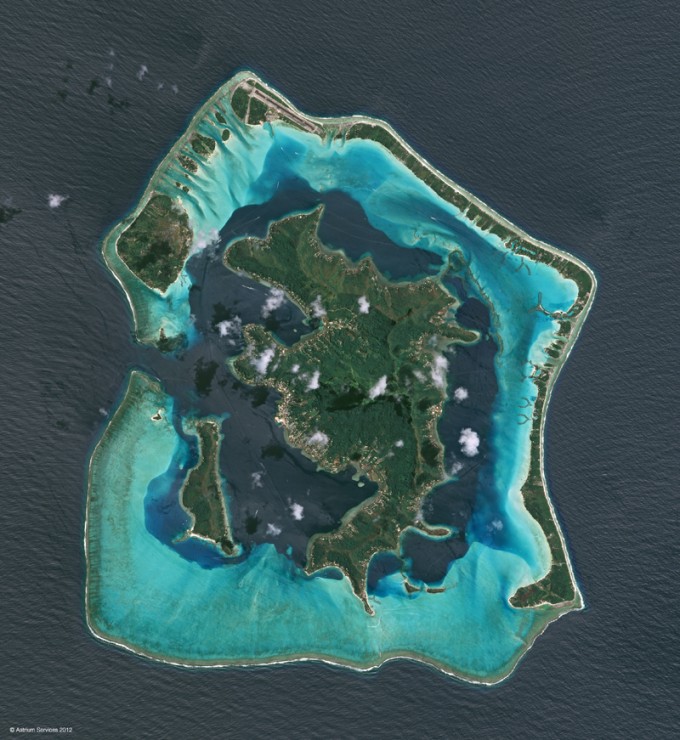
Bora Bora Islands, French Polynesia, taken by SPOT 6 three days after its launch. Source. Astrium
Spot Image, a subsidiary of Astrium, is funding the satellites SPOT 6 and SPOT 7 alone and owns the system (satellites and ground segments).
Spot satellites are used for civil and military purposes.
Source: GeoConnexion

#


Next article

 In the era of smartphones and smart devices, navigation in urban areas still remains a gray area where position accuracies (of around 5m) can be frustrating and misleading. Certainly all of us have experienced being misled to take a wrong turn because of this urban canyon problem. It’s amazing how 5 meters can make such a difference!
Why is the accuracy so bad in urban areas?
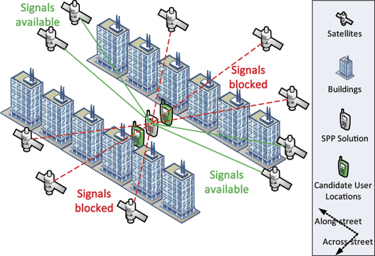
The reason for poor GNSS positioning accuracy is due to the lack of direct line-of-sight (LOS) signals from GNSS satellite constellations. Without direct signals, our smartphones and navigation devices are forced to use signals that have multipath in them. Despite many algorithms that totally neglect signals with multipath or use corrections, the accuracy is still not comparable to conditions where LOS signals are available. Although, Using GLONASS in addition to GPS does considerably enhance the availability of LOS signals it is still not going to solve the problem that arises due to signal geometry.
 We are surrounded by buildings that are parallel to the street, which means we are more likely to receive LOS signals from satellites that are along the satellite than across the street. This leads to position accuracy to be better along the street than across it. The end result is that, we will know accurately whether we are standing near door number 10 or 15 but we will have issues knowing whether it is the first street or the second.
How to solve this urban canyon problem in GNSS?
Well, we first need to accept the reality that so far we have not been able to come up with a better solution than GNSS to locate ourselves accurately on a global scale which means any solution that we think of, has to be able to take GNSS positioning as an input and better it; A solution that acts as a feedback loop mechanism rather than acting as a stand-alone solution.
Obviously we could then use INS (inertial navigation systems), iBeacons, WiFi signals, Mobile triangulation technique and maybe hundred other options but the technique that caught my attention – “GNSS Shadow Matching”! The GNSS Shadow Matching technique is currently being developed at the University College London by Dr. Groves and his team.
Improving GNSS positioning in urban canyons requires lateral thinking. If it’s not possible to calculate a sufficiently accurate position solution using the visible satellites, why not use the non visible satellites as well? This is exactly what shadow matching does. If you know where the buildings are and how big they are, you can deduce positional information from the knowledge that certain signals are blocked. – GPSWorld
The GNSS shadow matching technique makes use of 3D models of a city to accurately pinpoint your location. The principle behind shadow matching of GNSS signals is quite simple and straightforward, you know the building in front of which you are standing, thanks to 3D Building models and Image Processing. It is also possible to determine which satellites will have direct LOS to this building at any given point in time. We combine these two to determine our position with much better accuracy. Match the “shadow” signals with the actual signals that we are receiving and immediately our position accuracy is set to improve.
Quite Interesting right? Well, I cannot imagine using this technique tomorrow morning to navigate because of a couple of reasons, 3D models are not as widely available as much as we would like them to be. The drain on my poor smartphone battery if I have keep my camera turned on all the time. In conclusion, we still have to rely on using WiFi and Mobile Triangulation techniques to solve our urban navigation headache. However the GNSS Shadow Matching technique is still in its nascent stages and it would be foolish to write it off already. Who knows what the future holds in store 😉
If you want to read more about this interesting technique, here’s the link to the complete research article that also featured on the INSIDEGNSS magazine.