
The launch of high resolution radar satellites such as the German TerraSAR-X satellite (launched in summer 2006, resolution of 1m, 3m or 16m m depending on the recording mode) opened new possibilities in monitoring traffic flows from space. Indeed, the German Aerospace Centre (DLR) has developed and installed an automatic and already operational traffic processor at the TerraSAR-X ground segment. This processor is designed to automatically detect moving objects in Synthetic Aperture Radar (SAR) images, to assign it to an existing road network and the estimation of the velocity.
However, the detection of moving objects faces some difficulties, as the motion on ground provokes a shift of the object in the SAR image. Moving objects appear shifted from their actual road or network position: Cars or trucks seem to drive on fields; trains, which are well represented as whitish long lines (see figure below), are shifted into the surroundings of the actual tracks and also ships appear apart from their actual route (see second image below).
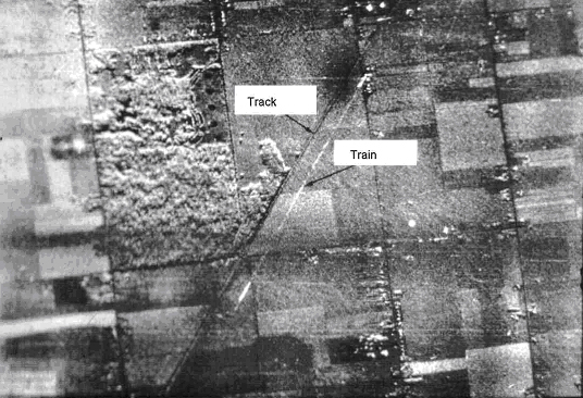
A moving train is not running on its (dark grey) tracks, but shifted to the right hand side in the SAR image.
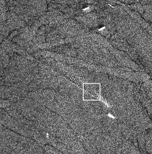
SeaSAR Image of a ship crossing the english channel. The ship at the front seems off its route. Source: W.Alpers
Where does the shift in SAR images come from?
Apart from the constallation of a satellite, the geometry of a sensor, the wave length and look angles, SAR processors take advantage of the Doppler frequency, which linearly changes from positive to negative values when the sensor passes a target object. Thereby, standard SAR-processing methods are based upon the assumption of a static scene or in other words the stationary of the detected objects. If the target has a velocity component, its doppler shift is changed compared with that from a stationary reflector. As a consequence the SAR gets confused and produces artefacts in the final image displacing the motion objects. The displacement depends on the moving direction of the individual objects: An object moving linearly in along–track (azimuth) direction causes a blurring in azimuth direction whereas an object moving in cross–track (range) direction causes mainly a displacement in azimuth direction. These imaging errors can be compensated for by detecting the moving objects, estimating their velocities and positions, and compensating for their motion.
Detecting moving objects in SAR images
Up to now, various methods for the detection and imaging of moving targets and the estimation of their real positions have been developed (see the literature below). For instance, multiple SAR-images or sub-apertures can be used for the detection of moving targets and the estimation of their velocity vectors. To detect moving objects and estimate their ground speed the DLR takes advantage from a geometric characteristic of the TerraSAR-X antenna: Two SAR antennas are spatially aligned in flight direction and separated by the along track baseline. This dual receive antenna mode electronically splits up the antenna into two parts in the along track direction upon receiving. As the satellite platform moves on with a certain velocity, both antennas map the same ground area with a temporal separation that is defined by the distance between the two antennas. In this manner the along track interferometry (ATI) becomes possible, which is sensitive to moving objects.
The list of papers at the bottom gives detailed information about the methods of detecting moving objects and estimating their ground speed in SAR imagery.
Suchandt S., Runge H., Breit H., Steinbrecher U., Kotenkov A. and Balss Ulrich, 2009: Automatic Extraction of Traffic Flows Using TerraSAR-X Along-Track Interferometry. IEEE TRANSACTIONS ON GEOSCIENCE AND REMOTE SENSING, VOL. 48, NO. 2, FEBRUARY 2010
Axelsson S., 2004: Position correction of moving targets in SAR-imagery. SAR Image Analysis, Modeling, and Techniques VI, edited by Francesco Posa, Proceedings of SPIE Vol. 5236 (SPIE, Bellingham, WA, 2004), doi: 10.1117/12.511213
Kirscht M., 1999: Estimation of velocity, shape and position of moving objects with SAR. Fourth International Airborne Remote Sensing Conference and Exhibition /21st Canadian Symposium on Remote Sensing, Ottawa, Ontario, Canada, 21–24 June 1999
Alpers W., 2008: SAR imaging of moving objects, including ships and ocean surface waves. ESA-MONRE/RSC Training Course Hanoi., 25 February – 7 March 2008
More literature:
R.K. Raney, 1971: Synthetic Aperture Imaging Radar and Moving Targets, IEEE AES-7, pp. 499-505.
R.K. Raney, 1971: Synthetic Aperture Imaging Radar and Moving Targets, IEEE AES-7, pp. 499-505.
K. Ouchi, 1985: On the Multilook Images of Moving Targets by SAR, IEEE AES-33, pp. 823-827.
J.R. Moreira, W. Keydel, 1995: A New MTI-SAR Approach Using the Reflectivity Displacement method, IEEE GRS-33, pp. 1238-1244.
J. Meyer-Hilberg, C. Gschössl, 1998: Detection and Repositioning of Moving Targets in SAR Images, Proc. International Radar Symposium, Munich.
R. Klemm, 1991: Adaptive Airborne MTI with Two-dimensional Motion Compensation, IEE Proc.-F , pp. 551-558.
J.H.G. Ender, 1996: Detection and Estimation of Moving Target Signals by Multi-Channel SAR, AEU Int. J: Electron. Commun. 50:2, pp. 150-156.
D.J. Coe, R.G. White, 1996: Experimental Moving Target Detection Results from a Three-Beam Airborne SAR, AEU Int. J: Electron. Commun. 50:2, pp. 150-156.
S. Barbarossa, A. Farina, 1994: Space-Time Processing of Synthetic Aperture radar Signals. IEEE AES-30, pp. 341-357.
S. Barbarossa: Detection and Imaging of Moving Objects with synthetic Aperture Radar. Part I: Optimal Detection and Parameter Estimation, IEE Proc.-F, February 1992, pp. 79-88.
S. Barbarossa, 1992: Detection and Imaging of Moving Objects with Synthetic Aperture Radar. Part II: Joint Time-Frequency Analysis by Wigner-Ville Distribution, IEE Proc.-F, pp. 89-97.
S. Werness, W. Carrara, L. Joyce and D. Franczak, 1990: Moving Target Imaging Algorithm for SAR Data., IEEE, vol, AES-26, no.1, pp. 57-67.
S. Barbarossa and A. Scaglione, 1998: Autofocusing of SAR Images Based on the Product high-order ambiguity function, IEE Proc.-F, pp. 269-273.
A. Rihaczek and S. J. Hershkowitz, 1996: Radar Resolution and Complex-Image Analysis. Artech House
R.P. Perry, R.C. DiPetro and R.L. Fante, 1999: SAR Imaging of Moving Targets, IEEE, vol. AES-35:1, pp. 188-200.
V.C. Chen and S. Qian, 1998: Joint Time-Frequency transform for Radar Range-Doppler Imaging. IEEE, vol. AES-34, no.2, pp. 486-499.
M. Soumekh, 2002: Moving target detection and imaging using an X-band along-track monopulse SAR, IEEE transactions on Aerospace and Electronic Systems, vol. 38, pp. 315-333.
M. Kirscht, 2003: Detection and imaging of arbitrary moving targets with single-channel SAR, Proc. IEE Radar Sonar Navig., vol. 150, pp. 7-11.
J.M.B. Dias and P.A.C. Marques, 2003: Multiple moving target detection and trajectory estimation using a single SAR sensor, IEEE Transactions on Aerospace and Electronic Systems, vol. 39, pp. 604-624.
S.R.J. Axelsson 1999, Methods for the detection and position correction of moving targets in SAR-images, Proc. Radio Science and Communication, RVK99, Karlskrona, Sweden, 14-17, pp. 150-156.

#


Next article

As high-fidelity sensors continue to become smaller and more compact, drones are now capable of carrying more payload options than ever before. With all these various models, picking the right one for each unique industrial use can feel overwhelming.
The best way to begin is to identify your specific needs by first determining the result that you want. What are you hoping to achieve? Once you have established your goals, selecting the best-suited sensor will come easily.
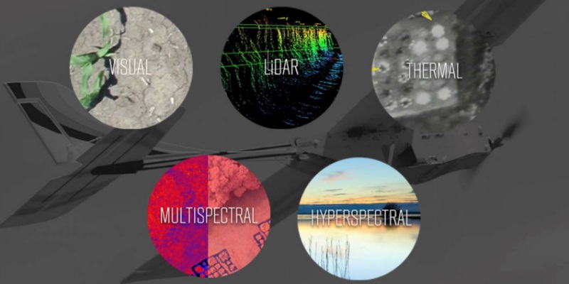
At PrecisionHawk, we are cognizant of the fact that better aerial information is highly dependent on the quality of data coming into the pipeline. For this reason, we offer a wide range of sensors and comprehensive data analysis tools that are unparalleled in today’s UAV market. Below is a brief overview of each sensor available, its industry applications and use cases.
The Sensor Applications Matrix is an easy-to-use guide that simplifies sensor selection for your industry needs. It represents a sampling of top drone applications, though the possibilities are virtually limitless. Click on the image to enhance.

Hyperspectral
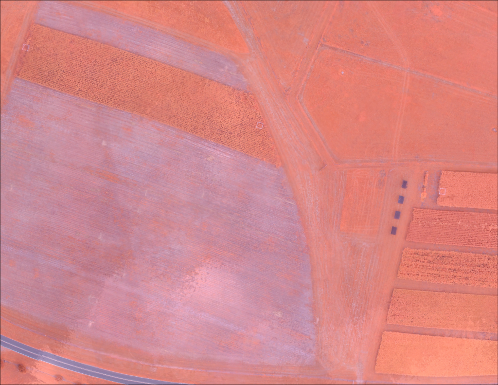
The completely integrated visible and near infrared Hyperspectral Sensor is perfect for small UAV applications. Hyperspectral provides more detailed information content with a capability to see the unseen in comparison to a visual camera. The line scanning (push broom) type sensor is perfect for research applications to measure the spectrography of the ground.
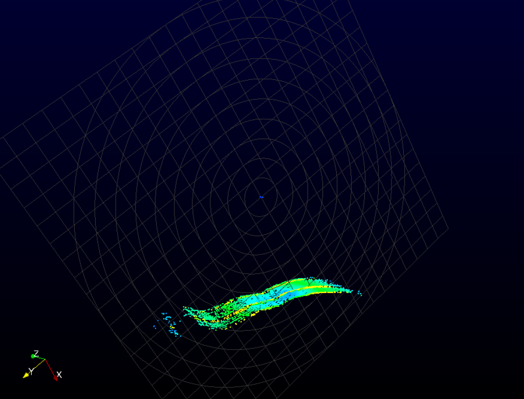
LiDAR
LiDAR is a more traditional surveying tool used for creating point clouds and digital elevation models of the ground. The data can be used for plant height measurement by comparing the first return from the laser when it hits the top of the plant to the last return when it hits the ground.The ability to penetrate foliage makes LiDAR unique compared to passive optical imagers that provide height data only from the canopy. The digital elevation models can be more accurate compared to visual sensor based digital elevation models, depending on the application.
Multispectral
The Multispectral Sensor is one of the most commonly used scanning systems. Like the Hyperspectral Sensor it’s able to see visible light, infrared radiation and ultraviolet light. We offer a 5 Channel Multispectral Sensor and a High Resolution Multispectral Imager. They range in the number of bands and resolutions, topping out at sub one centimeter per pixel.
Thermal Infrared (TIR)
Thermal Infrared Sensors have the ability to measure and read the surface temperature of land or objects beyond the scope of human vision. We offer two Thermal Infrared Sensor options, a High Resolution TIR-H and Radiometric High Resolution Thermal Sensor. Although the two sensors are very similar, a key difference is the High Resolution TIR-H sensor output is linear with temperature.
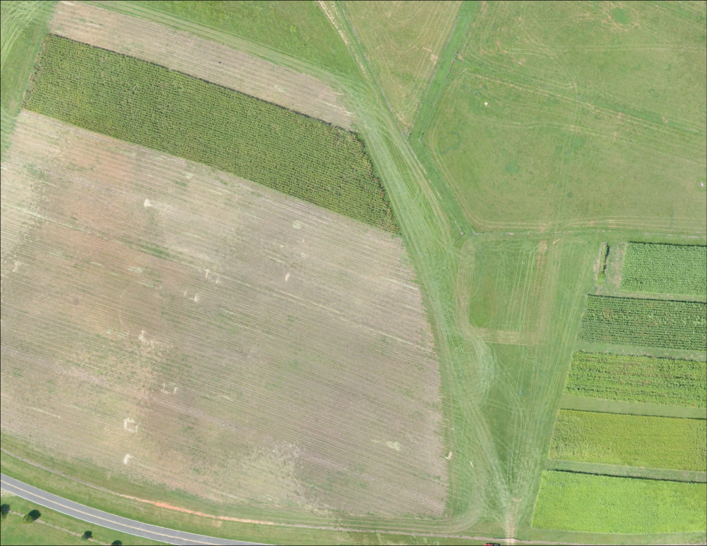
Visual
Both the Visual Sensor and Enhanced Resolution Visual Sensor are high-resolution, low-distortion RGB cameras which produces color imagery. A major advantage of visual imagery captured by a UAV is the aerial perspective of a specific area. You’re able to get a birds-eye-view high-res picture without putting in extra effort for the vantage point.
In a results driven climate, having a multitude of solutions available in one location eases the pressure when selecting the perfect sensor. We are constantly exploring advancements with the range of sensors we currently offer and creating innovative solutions to add more sensors to our existing line.